Presentation on INTELLIGENT HOME SECURITY SYSTEM
INTRODUCTION:
Considering some present problems of a building or an area in our
country, we have found that providing security is one of the main concerns. So
we thought about a security system which will help in providing continuous
safety to us and our assets. The basic aim of this project was to investigate
different ways of intruders breaking into residential areas and to adopt an
appropriate security system. We can protect our family and valuables with this
microcontroller based security system that will let us rest our head knowing
that should anyone trying to break into our home or building, an alarm will go
on and the security will be alerted immediately.
OBJECTIVES:
1. The
objectives of our project are as following:
2. To
provide security to the residential and commercial areas.
3. To detect
intruders entering into restricted regions.
4. To make a
reliable security system.
5. To make a
system with minimum cost and power consumption.
POSSIBLE OUTCOMES:
1. If a
person wants to enter into the secured area in a wrong manner, corresponding
LED and alarm will be on. The state is not changed until the system is reset.
2. If anyone
tries to break the door of a flat in the absence of the owner, the security
person will be alerted through the same process.
3. The
system is also capable to detect fire and there is also an IR pair in the room
to detect unwanted person in the house in the absence of the owner in case the
person enters through the window or in any other way.
4. There is
a switch to control the two IR pairs in the house because these two pairs will
be on if there is no one in the house.
OVERVIEW OF THE PROPOSAL
 |
OVERVIEW OF THE PROPOSAL
|
BLOCK DIAGRAM
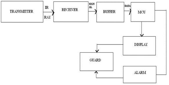 |
| BLOCK DIAGRAM |
CIRCUIT DIAGRAM:

ADVANTAGES:
1. Cheap
cost.
2. Negligible
power consumption.
3. Low maintenance
cost.
4. Flexible.
5. Reliability
of operation.
6. Low
installation cost.
7. Minimum
load variation.
LIMITATIONS:
1. Coverage
range of IR transmitters used are approximately 20 feet. So there will be need
of “repeaters” to cover large areas.
2. We have
proposed for a reliable system as far as we could have done. But like the other
security systems, it is also breakable.
3. There is
a chance of false alarm in the system but the probabilities are very small.
4. There is
an effect of sunlight on infrared communication between transmitter and the
receiver. The system is more reliable in the absence of daylight.
FUTURE DEVELOPMENTS:
1. With
proper research, the system can be made wireless.
2. We can
use CCTV with the existing system in order to increase reliability.
3. We can
also use flashlight and camera with proper zooming abilities.
4. By using
infrared lasers, we can increase the coverage area to a greater extent.
POWER CONSUMPTION:
For our project, the required dc voltage is approximately 5v and
the required current is about 0.16A. So the required power for one hour is 0.8
Wh. Power consumption in a day will be around 19.2 Wh and the power required in
a month will be 576 Wh or 0.576 KWh approximately. Sometimes the circuit may
vary in case of the required supply voltage but we can assume the variation as
constant. We can see that the project is very low power consuming which is one
of our main objectives.
CONCLUSION:
The microcontroller based home security system has been
introduced. Experimental results shows that the microcontroller is a reliable
instrument to control the system. The system is applicable to different sizes
of areas and high controlling capability over them. The simple design of it
allows minimum of maintenance work and the price performance relationship is
cost effective. Despite of having some limitations, our system is more
applicable in the prospective of our country.